
BRAKE MOTOR-2B
- Home
- BRAKE MOTOR-2B
Brake Motor
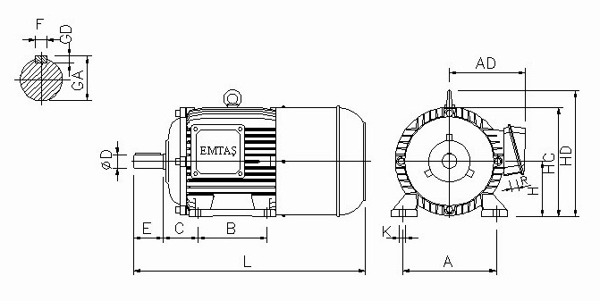
B3 ve B5 EXPLANATIONS OF DIMENSIONS REPRESENTED BY LETTERS ON ENGINE ASSEMBLY
| H | Distance from the centre-line of the shaft to the bottom of the feet (basic dimension) |
| A | Distance between centre-lines of fixing holes (end view). |
| B | Distance between the centre-lines of the fixing holes (side view). |
| C | Distance from the shoulder on the shaft at D-end to the centre-line of the mounting holes in the nearest feet. |
| AB | Over-all dimension across the feet (end view). |
| AC | Diameter of the machine |
| AD | Distance from the centre-line of the machine to extreme outside of the terminal box or other most salient part mounted on the side of the machine. |
| BB | Over-all dimension across the feet (side view). |
| HC | Distance from the top of the horizontal machine to the bottom of the feet. |
| HD | Distance from the top of the lifting eye, the terminal box or other most salient part mounted on the top of the machine to the bottom of the feet. |
| K | Diameter of the holes or width of the slots in the feet of the machine. |
| L | Overall length of the machine with a single shaft extension. |
| LC | Overall length of the machine when there is a shaft extension at N-end. |
| D | Diameter of the shaft extension at D-end. |
| E | Length of the shaft extension from the shoulder at D-end. |
| F | Width of the keyway of the shaft extension at D-end. |
| GA | Distance from the top of the key to the opposite surface of the shaft extension at D-end. |
| GD | Thickness of the key of the shaft extension at D-end. |
| R | Distance from the mounting surface of the flange to the shoulder on the shaft. |
| DB | Lifting ring screw thread size, used to lift the engine on some of our engines. |